
120 Volt Relay Wiring Diagram Free Wiring Diagram
1 Connecting Additional Devices to the Remote Turn On Wire 2 Constant to Momentary Output - Negative Input/Negative Output 3 Constant to Momentary Output - Negative Input/Positive Output 4 Constant to Momentary Output - Positive Input/Negative Output 5 Constant to Momentary Output - Positive Input/Positive Output 6
Five Pin Relay Wiring Diagram Collection
Relay wiring diagrams are designed to be easy-to-understand, providing a visual representation of the connections between components in an electrical system. The diagrams use symbols and labels to represent the components of the system, including resistors, capacitors, relays, switches, and other parts.

Ep27 Flasher Wiring Diagram Wiring Diagram
A relay wire diagram is an illustration of the wiring layout for a relay. It shows the components of the circuit as simplified shapes and the power and signal connections between them. A relay has a number of terminals, including a coil that gets energized when current is applied. When the coil is energized, the contacts of the relay close.

Siemens Overload Relay Wiring Diagram Free Wiring Diagram
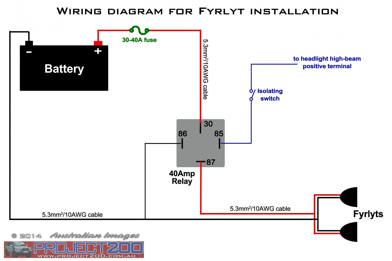
To wire in a split charge relay, the first step is to ensure the alternator and the batteries you are connecting share a negative charge. From there and using a wire connection, the positives on both batteries connect to the 87 and 30 pins on a split charge relay.

5 Pin Relay Wiring Diagram Use Of Relay
Basic Operation of Relay: Relay Wiring Diagram With Load: What is relay? Imagine, it's rainy season. It's raining cats & dogs outside. The whole environment becomes dark. Your mother tells you to switch on the incandescent bulb. But, you feel very dizzy. You are taking a rest with a blanket.
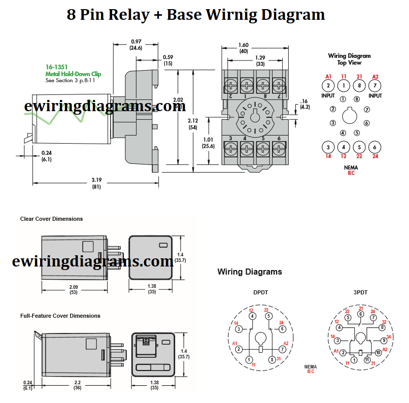
8 Pin Relay Base Wiring Diagram DPDT Relay Diagram
By following a complete diagram guide, you can easily wire a 4-wire relay in your electrical system. First, it is important to identify the control terminal, which receives a low-voltage signal to activate the relay. This terminal is usually labeled with an "C" or "Coil" symbol.

5 Pin Relay Wiring Diagram Fuel Pump
1.5K Share 53K views 11 months ago Automotive Wiring How-To's *PARTS LIST IN DESCRIPTION BELOW* 5 pin relay wiring can be done many different ways. The two most common ways to wire a 5 pin.
Gallery 5 Prong Relay Wiring Diagram Fresh 4 Pin Electrical Outlet 5
How To Wire A Relay Let's discuss how to wire a relay and go through the concepts of how a relay works. A relay is basically a switch but not like a switch that's on a wall. A wall switch relies on someone to flip it which will then control a light or some other type load. A relay is switched by electrical power and not a human.

12+ 6 Pin Flasher Relay Wiring Diagram Robhosking Diagram
4-Pin Relays Relay Wiring Diagram What is a Relay? As mentioned earlier, a relay is essentially a switch. Unlike a traditional switch, which we flip or toggle to make it ON and OFF, a relay is an electromechanical switch. The 'mechanical' action of moving the switch between ON and OFF positions is achieved by an 'electrical' signal.
Bosch Relay Wiring Diagram 5 Pole Manual EBooks 5 Prong Relay
This is a video tutorial on how exactly to wire a relay, how it works, why you would want to use one, and a demonstration in a practical application. By the.

120 Volt Relay Wiring Diagram Free Wiring Diagram
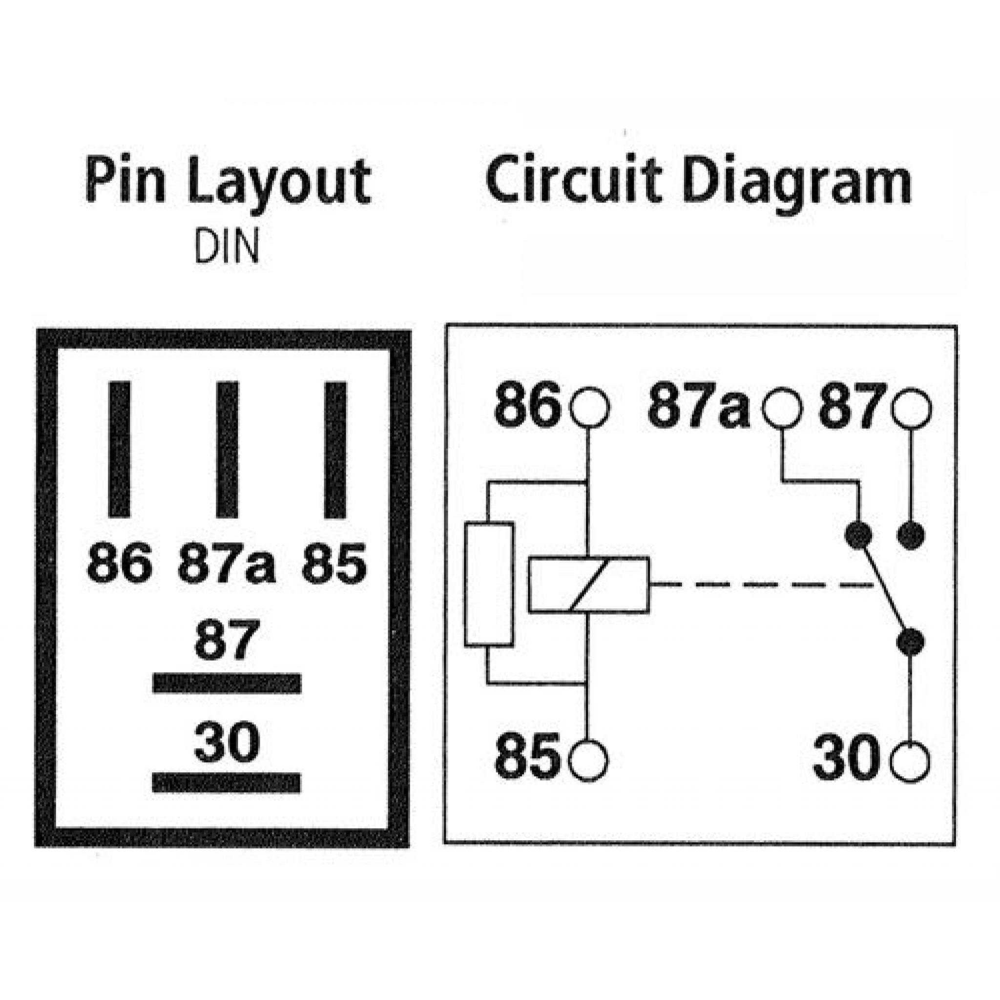
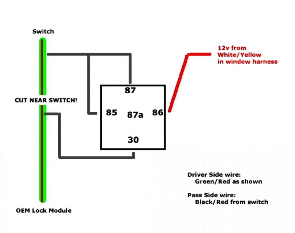
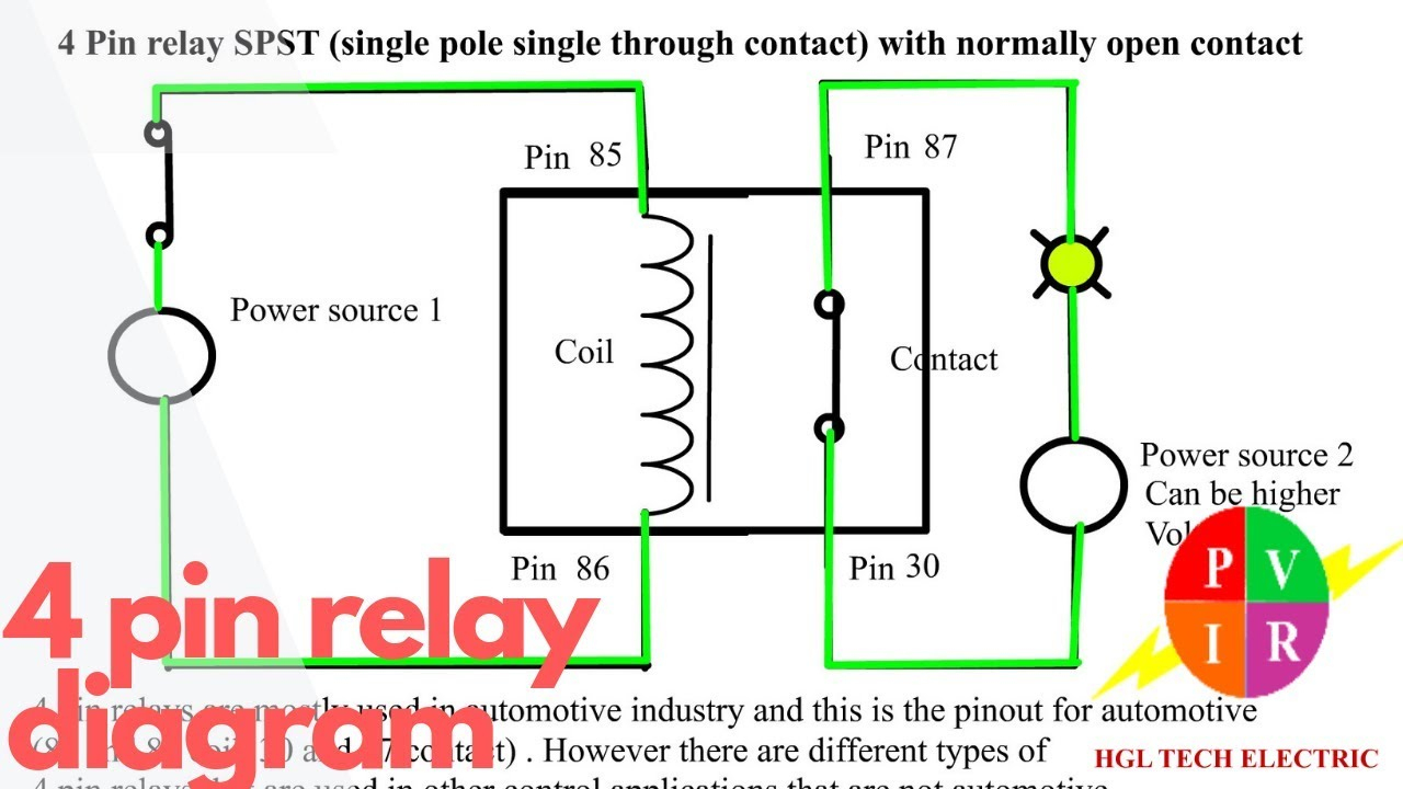
Step 1: Check the Wiring Diagram 12V relays normally have a wiring diagram printed on them like the one below to ensure you make the connections properly. Video | HotRodHippie In a typical 5-pin 12V relay: Pins 85 and 86 receive the trigger current. They might be marked 'COIL'.

Idec Sy4s 05 Wiring Diagram Free Wiring Diagram
Relay Wiring Diagram | Relay Connection | Relay Working Principle |A Relay is an electromechanical device that can be used to make or break an electrical con.

Relay Wiring Diagram and Function Explained ETechnoG
1 Use a relay and wires with the capacity for your vehicle and device. If you're replacing a worn relay, this is simple—just use an identical relay to the one you're ditching. Consult your vehicle's service manual (not the owner's manual) for specifications, or look at the outside of the relay.

[DIAGRAM] 3 Pin Horn Relay Diagram Wiring Schematic FULL Version HD
When wiring a relay, check the wiring diagram first and identify its terminals. Then, wire the relay terminals and complete the rest of the circuit accordingly. Here are the steps: Steps for wiring a relay Relay pin layouts and functions are not standard, so they may vary between manufacturers.
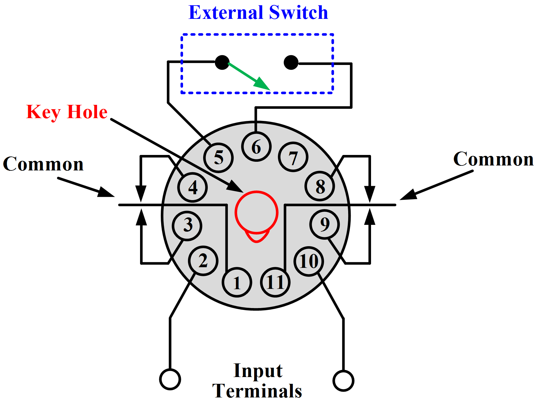
Wiring Diagram For 11 Pin Relays Wiring Diagram
how to understand why diagrams for relays simplified for beginners this explains how the load side and the control side of a relay works and how a short the.
4 Pin Wiring Diagram Cadician's Blog
It is commonly used for controlling lights, fans, motors, and other electrical devices that require a higher current to operate. When wiring a 12 volt relay, it is important to follow the schematic diagram provided by the manufacturer. This diagram shows the connections and components required to properly control the relay.